|
|
MCP41010, MPC41050, MPC41100 digital potentiometer with Arduino MEGA
A digital potentiometer (also called a resistive digital-to-analog converter,[1] or informally a digipot) is a digitally-controlled electronic component that mimics the analog functions of a potentiometer. It is often used for trimming and scaling analog signals by microcontrollers.
The name of the chip depends on the max value of the potentiometer and the number of them inside the chip:
-
MPC41010: single potentiometer, 10 kohm
-
MPC41050: single potentiometer, 50 kohm
-
MPC41100: single potentiometer, 100 kohm
-
MCP42010: two independent potentiometers, 10 kohm
-
MCP42050: two independent potentiometers, 50 kohm
-
MCP42100: two independent potentiometers, 100 kohm
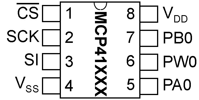
Pinout diagram
-
Pin 1 – CS – Chip Select. When low, the chip will will receive commands from the Serial Input at pin 3.
-
Pin 2 – SCK – Serial Clock. Clock input from the micro-controller that synchronizes serial communications.
-
Pin 3 – SI – Serial Input. Receives commands from the micro-controller when CS at pin 1 is low.
-
Pin 4 – Vss – Negative Supply or Ground.
-
Pin 5 – PA0 – Potentiometer Terminal A.
-
Pin 6 - PWO – Potentiometer Wiper
-
Pin 7 – PAB – Potentiometer Terminal B.
-
Pin 8 – Vdd – Positive Supply or Ground.
SPI
Serial Peripheral Interface (SPI) is a synchronous serial data protocol used by microcontrollers for communicating with one or more peripheral devices quickly over short distances. It can also be used for communication between two microcontrollers.
With an SPI connection there is always one master device (usually a microcontroller) which controls the peripheral devices. Typically there are three lines common to all the devices:
- MISO (Master In Slave Out) - The Slave line for sending data to the master
- MOSI (Master Out Slave In) - The Master line for sending data to the peripherals
- SCK (Serial Clock) - The clock pulses which synchronize data transmission generated by the master
and one line specific for every device:
- SS (Slave Select) - the pin on each device that the master can use to enable and disable specific devices.
When a device's Slave Select pin is low, it communicates with the master. When it's high, it ignores the master. This allows you to have multiple SPI devices sharing the same MISO, MOSI, and CLK lines.
Connections
| Arduino / Genuino Board |
MOSI |
MISO |
SCK |
SS (slave) |
SS (master) |
Level |
| Uno or Duemilanove | 11 or ICSP-4 | 12 or ICSP-1 | 13 or ICSP-3 | 10 | - | 5V |
| Mega1280 or Mega2560 | 51 or ICSP-4 | 50 or ICSP-1 | 52 or ICSP-3 | 53 | - | 5V |
| Leonardo | ICSP-4 | ICSP-1 | ICSP-3 | - | - | 5V |
| Due | ICSP-4 | ICSP-1 | ICSP-3 | - | 4, 10, 52 | 3,3V |
| Zero | ICSP-4 | ICSP-1 | ICSP-3 | - | - | 3,3V |
| 101 | 11 or ICSP-4 | 12 or ICSP-1 | 13 or ICSP-3 | 10 | 10 | 3,3V |
| MKR1000 | 8 | 10 | 9 | - | - | 3,3V |
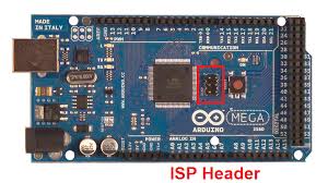
Note that MISO, MOSI, and SCK are available in a consistent physical location on the ICSP header; this is useful, for example, in designing a shield that works on every board.
|
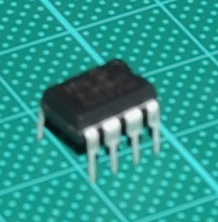
MCP41010 ic
|
|
|
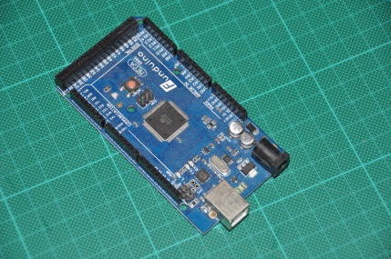
Arduino MEGA
|
|
|
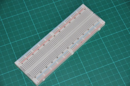
Breadboard
|
|
|
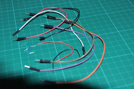
Wire
|
|
|
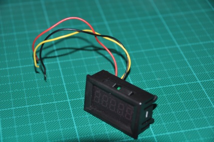
Voltmeter
|
|
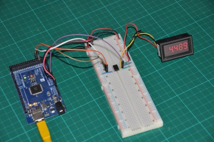
Project
|
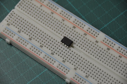
Place the MCP41010 ic
|
|
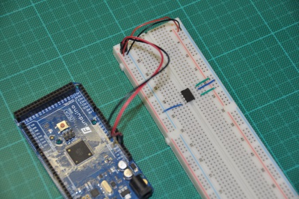
Wire 5v and GND
| MCP41010 | Arduino |
| VSS | GND |
| VCC | 5V |
| PB0 | GND |
| PA0 | 5V |
|
|
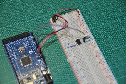
Connect wiper (PW0) to Ardiono analog A1.
|
|
Wire SPI
| MCP41010 | Arduino |
| CS | 53 |
| SCK | 52 |
| SI | 51 |
|

|
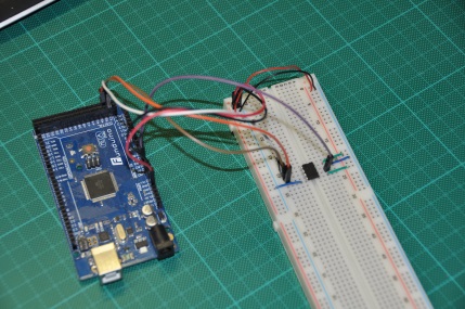
Wire voltmeter
|
Code
#include <SPI.h>
const int CS = 53;
int PotWiperVoltage = 1;
int RawVoltage = 0;
float Voltage = 0;

void setup() {
  pinMode (CS, OUTPUT);
  Serial.begin(9600);
  SPI.begin();
}

void loop() {
  // move the potentiometer in one direction
  for (int level = 0; level < 255; level++)
  {
    MCP41010Write(level);
    delay(100);
    RawVoltage = analogRead(PotWiperVoltage);
    Voltage = (RawVoltage * 5.0 )/ 1024.0;
    Serial.print("Level = " );
    Serial.print(level);
    Serial.print("\t Voltage = ");
    Serial.println(Voltage,3);
  }
  delay(2000);  // wait a couple seconds
  // Now mover potentiometer in other directions

  for (int level = 255; level > 0; level--)
  {
    MCP41010Write(level);
    delay(100);
    RawVoltage = analogRead(PotWiperVoltage);
    Voltage = (RawVoltage * 5.0 )/ 1024.0;
    Serial.print("Level = " );
    Serial.print(level);
    Serial.print("\t Voltage = ");
    Serial.println(Voltage,3);
  }
   delay(2000);
}

void MCP41010Write(byte value)
{
  // Note that the integer vale passed to this subroutine
  // is cast to a byte

  digitalWrite(CS,LOW);
  SPI.transfer(B00010001); // This tells the chip to set the pot
  SPI.transfer(value);     // This tells it the pot position
  digitalWrite(CS,HIGH);
}
Download code
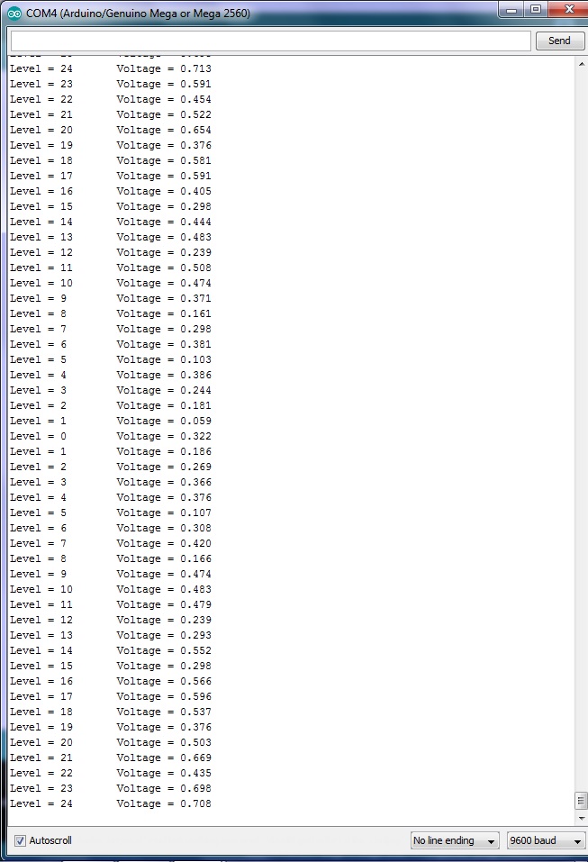
Monitor output
|