19. LED strip WS2812
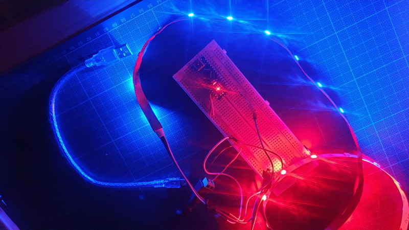
WS2812 is a intelligent control LED light source that the control circuit and RGB chip are integrated in
a package of 5050 components. It internal include intelligent digital port data latch and signal reshaping amplif
ication drive circuit. Also include a precision internal oscillator and a 12V voltage programmable constant curre
-nt control part, effectively ensuring the pixel point light color height consistent.
The data transfer protocol use single NZR communication mode. After the pixel power-on reset, the DIN
port receive data from controller, the first pixel collect initial 24bit data then sent to the internal data latch,
the other data which reshaping by the internal signal reshaping amplification circuit sent to the next cascade
pixel through the DO port. After transmission for each pixel,the signal to reduce 24bit. pixel adopt auto resha
-ping transmit technology, making the pixel cascade number is not limited the signal transmission, only depend
on the speed of signal transmission.
LED with low driving voltage, environmental protection and energy saving, high brightness, scattering angl
e is large, good consistency, low power, long life and other advantages. The control chip integrated in LED
above becoming more simple circuit, small volume, convenient installation. (WS2812.pdf)
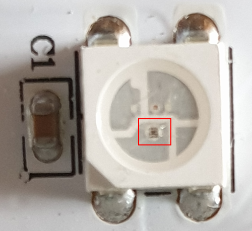
LED driver chip
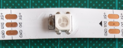
Each LED has three connectors at each end, two for the powering and one for the data. The arrow indicates the data flow direction. The data output pad of the previous LED is connected to the Data Input pad of the next LED. We can cut the strip to any size we want, as well as distance the LEDs using some wires.

Grey: GND
Green: Do/DIN, Green is connect to a digital pin
Red:+5V
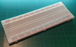 |
Breadboard |
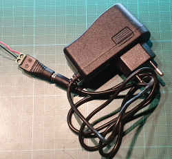 |
Adaptor
5V, 2A |
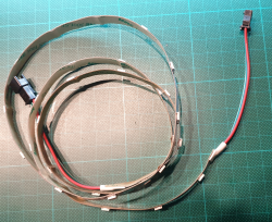 |
WS2812
White PCB
1m
30 5050
IP30 |
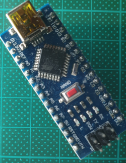 |
Arduino Nano |
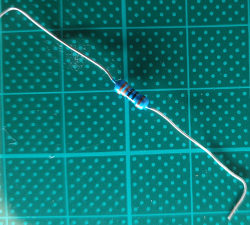 |
Resistor
330 Ohm |
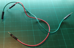 |
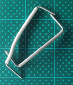
Jumpers |
 |
|
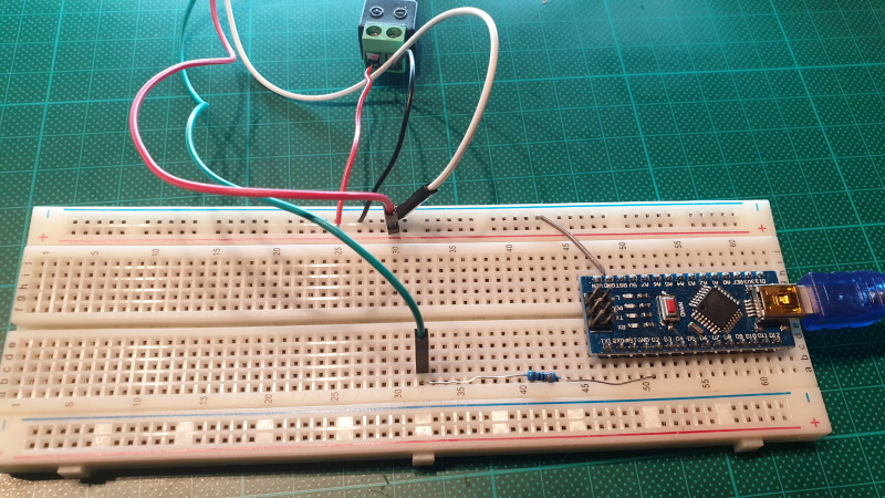
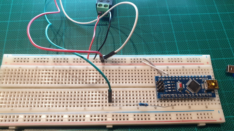
- Put the nano on the breadboard
-
Adaptor GND = ground rail
5V => power rail
- WS2812 Green => Resistor => Arduino D2
- WS2812 Red (5V) => Power rail
- WS2812 White (GND) => GND rail
- Arduino Nano => GND rail
-
Arduino Nano power:
USB computer
Arduino 5V => 5V rail
Power from USB computer
Power from adaptor
Simple blink sketch:
#include <FastLED.h>
#define LED_PIN     2
#define NUM_LEDS    30
CRGB leds[NUM_LEDS];
void setup() {
  FastLED.addLeds<WS2812, LED_PIN, GRB>(leds, NUM_LEDS);

}
void loop() {
  leds[0] = CRGB::Red;
  FastLED.show();
  delay(500);
  leds[0] = CRGB::Black;
  FastLED.show();
  delay(500);
}
#include <FastLED.h>
Include fastlib library.
download version 3.4.0
#define LED_PIN 2
digitale pin of arduino nano. (in)
#define NUM_LEDS 30
Number of LEDs
CRGB leds[NUM_LEDS];
Array of LEDs, type of CRGB
FastLED.addLeds
(leds, NUM_LEDS);
Add led-definitie to the class FalstLED. WS2812 => LED strip type. LED_PIN => digital pin of arduino, GRB => swap R and G, leds => array of the leds, NUM_LEDS => Number of leds
leds[0] = CRGB::Red;
First LED gets color red
FastLED.show();
Update the LEDS on the strip
delay(500)
Wait half a second
Download blink sketch
#include <FastLED.h>
#define LED_PIN     2
#define NUM_LEDS    30
#define BRIGHTNESS  255
CRGB leds[NUM_LEDS];
void setup() {
  randomSeed(analogRead(0));
  FastLED.addLeds<WS2812, LED_PIN, GRB>(leds, NUM_LEDS);
  FastLED.setBrightness(BRIGHTNESS );
}
void loop() {
  for (int i = 0; i <= NUM_LEDS; i++) {
    leds[i] = CRGB ( 0, 0, 255);
    FastLED.show();
    delay(10);
  }

   byte r = random(3, 100);
   r=255;
   byte g = random(3, 100);
   byte b = random(3, 100);
   int d = 10;
   for (int i = NUM_LEDS; i >= 0; i--) {
    leds[i] = CRGB ( r, g, 0);
    FastLED.show();
    if (r<229) r+=10; else r=255;
    if (g<239) g+=5; else g=255;
    if (b<200) b+=20; else b=255;
    delay(d);
    d+=(2 * i);
  }
}
Download sketch
download version 3.4.0
download WS2812.pdf
LedStrip Info
WS2812 Power Consumption