|
|
MCP23017 I/O Expander
This MCP23017 Arduino tutorial shows you how to control the device in driving LEDs and reading button presses. It also shows you exactly how to use interrupts which is very tricky as there are some problems (solved here) in using existing Arduino code.
The MCP23017 is a port expander that gives you virtually identical PORTS compared to standard microcontrollers e.g. Arduino or PIC devices and they even include interrupts.It gives you an extra 16 I/O pins using an I2C interface as well as comprehensive interrupt control. This is a very versatile and multi-configurable I/O expander. By adding more devices you can increase the total I/O to 128 pins still using only two I2C pins!.
Having interrupt outputs is one of the most important features of the MCP23017, since the microcontroller does not have to continuously poll the device to detect an input change. Instead an interrupt service routine can be used to react quickly to an input change such a key press etc.
MCP23017 Specifications:
| Power Supply | 1.8V ~ 5.5V |
| Supply Current (idle) | 1mA |
| Operational Current Max out of Vss | 150mA |
| Operational Current Max into Vdd | 125mA |
| Output current per pin | 25mA |
| Standby Current | 1uA |
| I2C address | 0x20 ~ 0x27 |
Pin definition for MCP23017 library
Note: In the library pins are labelled from 0 to 15 where:
pin 0 is bit 0 of port A
pin 7 is bit 7 of port A
pin 8 is bit 0 of port B
pin 15 is bit 7 of port B
MPC23017 I/O control functions
Single Bit I/O
Similar member functions to the pin controls on the Arduino are used to control the MCP23017 pins:
mcp.pinMode(0, OUTPUT);
mcp.digitalWrite(0,HIGH);
mcp.digitalRead(0);
Connections:
The following netlist and diagram show you how connecting the MCP23017 to the Arduino is very simple.
Connect pin #12 of the expander to Arduino Analog 5 (i2c clock)
Connect pin #13 of the expander to Arduino Analog 4 (i2c data)
Connect pin #19 of the expander to Arduino pin 3 (interrupt input).
Connect pins #15, 16 and 17 of the expander to Arduino ground (address selection)
Connect pin #9 of the expander to Arduino 5V (power)
Connect pin #10 of the expander to Arduino ground (common ground)
Connect pin #18 of the expander through a ~10kohm resistor to 5V (reset pin, active low).
Connect pin #28 of the expander to +ve end of an LED then to a~1kohm resistor to GND (MCP_LED1).
Connect pin #26 of the expander to +ve end of an LED then to a~1kohm resistor to GND (MCP_LEDTOG1).
Connect pin #4 of the expander to +ve end of an LED then to a~1kohm resistor to GND (MCP_LEDTOG2).
Connect pin #1 of the expander to a normally open push button that then connects to GND (MCP_INPUTPIN).
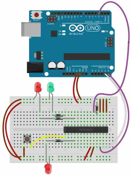
This example shows three LEDs on different ports of the MCP23017, with two on port A (Green and Red). Two LEDs are alternately flashed (Red ones) while the third shows the state of the input on GPB0 i.e GPB0 is read by the Arduino and then the Green LED is updated. This shows independent control of individual port bits i.e. while flashing the red LEDs the button is read and the green one is updated.
Code:
// MCP23017 Example: Slow key press reaction.
//
// Toggle LEDs and detect keypress.
//
// Example code showing slow reaction of 'button'
// LED to keypress. Leading into why interrupts
// are useful (See next example).
//
// Copyright : John Main
// Free for non commercial use.

#include <Wire.h>
#include <Adafruit_MCP23017.h>

#define MCP_LED1 7
#define MCP_INPUTPIN 8
#define MCP_LEDTOG1 11
#define MCP_LEDTOG2 4

Adafruit_MCP23017 mcp;

void setup() {
  mcp.begin();      // Default device address 0

  mcp.pinMode(MCP_LEDTOG1, OUTPUT);  // Toggle LED 1
  mcp.pinMode(MCP_LEDTOG2, OUTPUT);  // Toggle LED 2

  mcp.pinMode(MCP_LED1, OUTPUT);     // LED output
  mcp.digitalWrite(MCP_LED1, HIGH);

  mcp.pinMode(MCP_INPUTPIN,INPUT);   // Button i/p to GND
  mcp.pullUp(MCP_INPUTPIN,HIGH);     // Puled high to ~100k
}

// Alternate LEDTOG1 and LEDTOG2.
// Transfer pin input to LED1.
void loop() {

  delay(300);

  mcp.digitalWrite(MCP_LEDTOG1, HIGH);
  mcp.digitalWrite(MCP_LEDTOG2, LOW);

  delay(300);

  mcp.digitalWrite(MCP_LEDTOG1, LOW);
  mcp.digitalWrite(MCP_LEDTOG2, HIGH);

  // Transfer input pin state to LED1
  if (mcp.digitalRead(MCP_INPUTPIN)) {
     mcp.digitalWrite(MCP_LED1,HIGH);
  } else {
     mcp.digitalWrite(MCP_LED1,LOW);
  }

}
Now work on using the I/O pins as digital inputs. The MCP23017 I/O pins default to input mode, so we just need to initiate the I2C bus. Then in the void loop() or other function all we do is set the address of the register to read and receive one byte of data.
For our next example, we have our basic sketch as described at the start of this article using four normally-open buttons (once again using the ‘button board‘) which are connected to port B inputs 0~3. Consider the first five lines of void loop() in the following example:
/*
 Example 41.2 - Microchip MCP23017 with Arduino
 http://tronixstuff.com/tutorials > chapter 41
 John Boxall | CC by-sa-nc
 */
// pins 15~17 to GND, I2C bus address is 0x20
#include "Wire.h"
byte inputs=0;
void setup()
{
 Serial.begin(9600);
 Wire.begin(); // wake up I2C bus
}
void loop()
{
 Wire.beginTransmission(0x20);
 Wire.write(0x13); // set MCP23017 memory pointer to GPIOB address
 Wire.endTransmission();
 Wire.requestFrom(0x20, 1); // request one byte of data from MCP20317
 inputs=Wire.read(); // store the incoming byte into "inputs"
 if (inputs>0) // if a button was pressed
 {
 Serial.println(inputs, BIN); // display the contents of the GPIOB register in binary
 delay(200); // for debounce
 }
}
Simple Not ok:
#include "Adafruit_MCP23017.h"
Adafruit_MCP23017 mcp1;
Adafruit_MCP23017 mcp2;
void setup() {
mcp1.begin(0);
mcp2.begin(1);

mcp1.pinMode(0, INPUT);
mcp1.pinMode(1, OUTPUT);
mcp2.pinMode(1, OUTPUT);
Serial.begin(9600);
pinMode(13, OUTPUT);
}

void loop() {
mcp2.digitalWrite(1, mcp1.digitalRead(0));
digitalWrite(13, mcp1.digitalRead(0));
mcp1.digitalWrite(1, mcp1.digitalRead(0));
if(mcp1.digitalRead(1) == HIGH){
Serial.println("Led whent HIGH");
}
}
Multiple MCP23017
The MCP Address column refers to the address used by the Adafruit driver
chip
address hardwired address i2c
address MCP
address
A2 A1 A0
000 GND GND GND 0x20 0
001 GND GND 5v 0x21 1
010 GND 5v GND 0x22 2
011 GND 5v 5v 0x23 3
100 5v GND GND 0x24 4
101 5v GND 5v 0x25 5
110 5v 5v GND 0x26 6
111 5v 5v 5v 0x27 7
ref:
www.best-microcontroller-projects.com
tronixstuff.com
Download:
Adafruit-MCP23017-Arduino-Library-master
Datasheet
example41p2
|