A4988
How To Control NEMA17 Stepper Motor with Arduino and A4988 Stepper Driver
Generally, the NEMA17 stepper motor has 200 steps, or 1.8 degrees per step resolution, but there are also models with 400 steps and 0.9 degrees per step resolution.
The number stands for the size of faceplate in inches when divided by 10, or in this case that would be 17 divided by 10 equals 1.7 inches faceplate, or 2.3 inches faceplate in case of NEMA23.
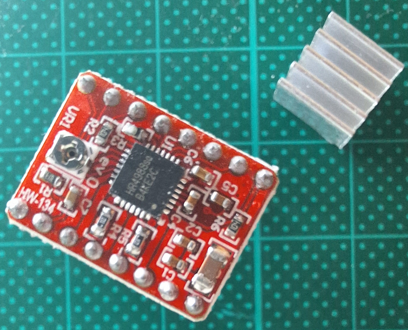
The A4988 has a maximum current rating of 2A per coil, but that’s actually a peak rating. It is recommended to keep the current to around 1A, but of course, it is also possible to go up to 2A of good cooling is provided to the IC.
A great feature the A4988 stepper driver has, actually all other drives have, is the current limiting. With this we can easily set how much current the motor will draw no matter the motor rating. For example, we can connect even a 2.5A rated stepper motor, but we will limit the current of the driver to 1.5A. So, although the motor won’t work at its maximum capacity, we would still be able to use it.
On the other hand, if the motor is rated lower than the set current limit on the driver, the motor would overheat. Of course, it’s always recommended to try to match the current rating of the motor with the current rating of the driver.
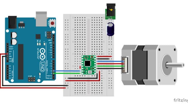
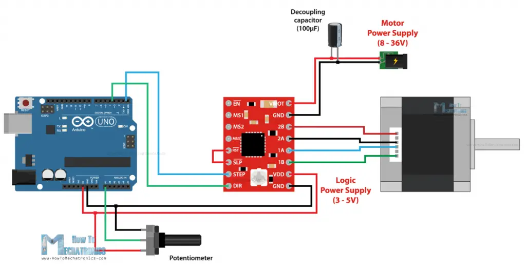
A4988 and Arduino Connection
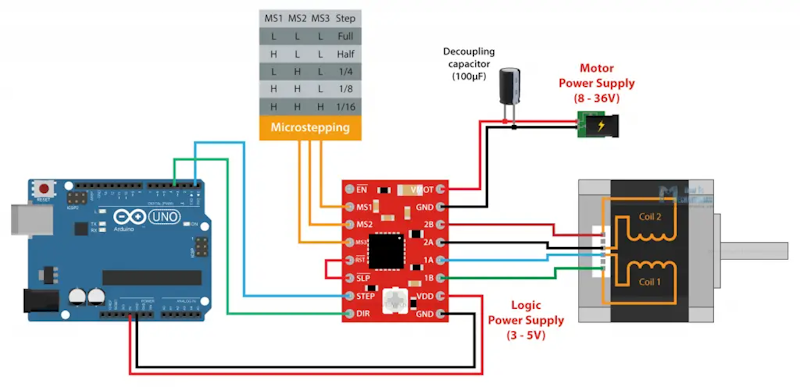
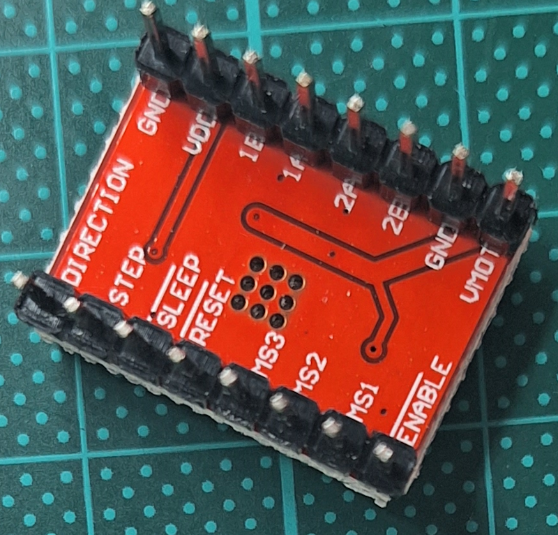
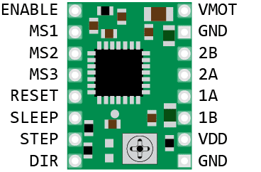
At top right corner of the driver we have the VMOT and GND pins and here we connect the power supply for the motor which can range 8 to 36V. Here it is also recommended to use a decoupling capacitor across these two pins in order to protect the board from voltage spikes. We should use large electrolytic capacitor with at least 47uF capacity.
Next, are the four pins where we connect the stepper motor. One phase of the motor goes on 1A and 1B pins, and the other phase on 2A and 2B pins.
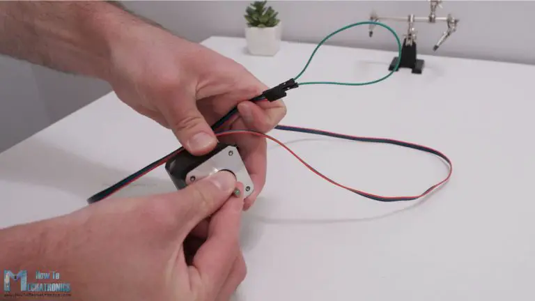
Sometimes, it can be a bit difficult to recognize which two wires of the motor make a phase, but are several ways to identify them. The simplest way is to rotate the shaft of the stepper motor by hand, and then connect two wires to each other. If you connect two wires that make a phase, the rotation of the shaft would be a bit more difficult.
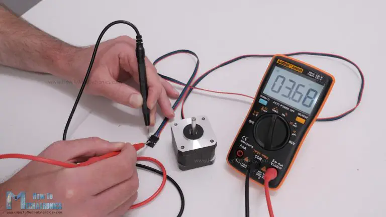
Another way is to use a multimeter and check for continuity between the two wires. If you connect two wires that make a phase, you will have a short circuit and the multimeter will start beeping.
Once we find a phase, we can connect it to any position of the two positions on the driver, the order doesn’t matter.
Next, we have the IC or the logic power supply pins, VDD and GND, which can be from 3V to 5V. On the other side we have the Step and the Direction pins, which can be connected to any pin of the Arduino board. With the Direction pin we select the rotation direction of the motor, and with the Step pin we control to steps of the motor. With each pulse we send to the Step pin, the motor will advance one step in the selected direction.
Right above these pins, we have the Sleep and the Reset pins which are used for, as their names suggest, putting the driver to sleep mode or resetting it. We should note that both of these pins are active low. The Sleep pin by default is HIGH state, but the RST pin is floating. That means in order to have the driver enabled, the easiest way is to just connect these two pins to each other, assuming we won’t use these pins functions.
The Enable pin is also active low, so unless we pull it HIGH, the driver will be enabled.
The next three pins, MS1, MS2 and MS3, are for selecting the step resolution of the motor. We already said that the step resolution depends on the construction of the motor which is usually 200 steps per revolution for a NEMA 17 stepper motor. However, all stepper drivers have this feature called microstepping which allows driving the motor at higher resolutions. This is achieved by energizing the coils at an intermediate current level, which produce intermediate step locations.
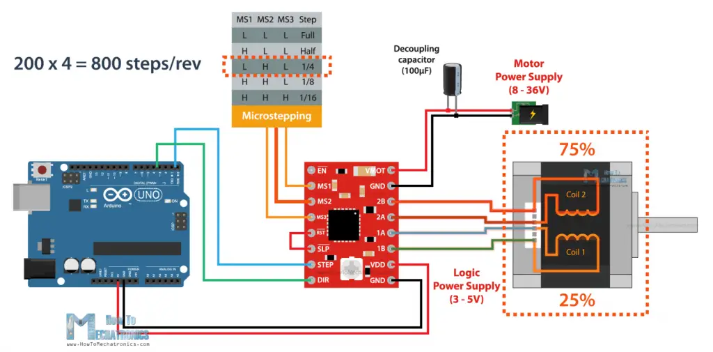
For example, if we select quarter-step resolution, the 200 steps of the motor will become, 200 multiplied by 4 equals 800 microsteps per revolution. The driver will use four different current levels on the coils to achieve this.
The A4988 driver has a maximum resolution of 16 microsteps, which would make a 200 steps NEMA17 motor has 3200 steps per revolution, or that’s 0.1125 degrees per step. That’s really impressive precision and that’s why these types of stepper motors and drivers are used in so many applications. Actually, there are stepper drivers that have up 256 microsteps, or that’s a whopping 51200 steps per revolution, or 0.007 degrees per step.
Nevertheless, these three pins have pull-down resistors, so if we leave them disconnected, the driver will work in full-step mode. For selecting a different mircrostepping resolution we need to connect 5V to the appropriate pins according to this table.
A4988 Current Limiting
All right, so now that we know how to connect the stepper motor and the driver to the Arduino board, we can move on with explaining how to program or code the Arduino for controlling the stepper. However, before we do that, or before we power the motor, there is one more very important thing that we need to do, and that’s to adjust the current limit of the driver.
As we already explained, we need to adjust the current limit of the driver to be lower than the current rating of the motor, or otherwise the motor would overheat.
There’s a small trimmer potentiometer on the A4988 driver though which we can adjust the current limit. By rotating the potentiometer clockwise, the current limit raises, and vice versa. There are two methods which can be used for determining the actual value of the current limit.
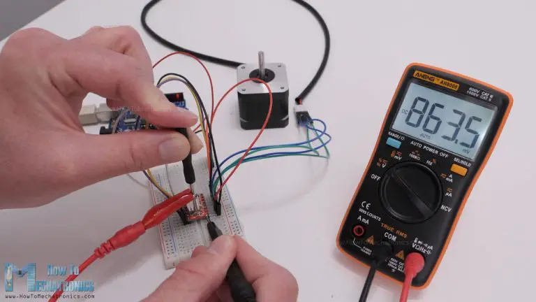
The first method involves measuring the reference voltage across the potentiometer itself and GND. We can measure the reference voltage using a multimeter, and use that value in the following formula to calculate the current limit of the driver:
Current Limit = Vref / (8 x Rcs)
The Rcs is the current sense resistance or the values of the current sensing resistors located right next to the chip. Depending on the manufacturer, these values are usually 0.05, 0.1 or 0.2 ohms. So, we need to take a closer look at the value of these resistors in order to accurately calculate the current limit with this method. In my case, these resistors were labeled R100, which meant 0.1ohms.

As an example, if we measure a reference voltage of 0.7V, and we have 0.1 ohms resistors, the current limit would be a 0.875A. Or if we want to limit the current to, let’s say 1A, we should adjust the reference voltage to 0.8V.
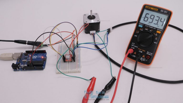
The second method for setting the current limit is by directly measure the current through the coils. For that purpose, we need to connect the stepper motor and the driver as explained previously. We can skip the controller connection, but instead connect 5V to the Direction and the Step pins so that the motor stays active and holds one position. The MS pins should be left disconnected so the driver would work in full-step mode. Then we can disconnect one line or coil from the motor, and connect it in series with an ammeter. In this way, once we power the driver with both the logic voltage, the 5V, and the power for the motor 12V in my case, we can read how much current is running through the coil.
 >br>
>br>
Though, we should note here that when the driver works in full-step mode, the current in the coils can reach only 70% of the actually current limit. So, when using the driver in the other microstepping modes, the reading from the ammeter should be multiplied by 1.3 in order to get the actual value of the current limit of the driver.
I tried both methods for setting up the current limit of the driver and they gave me approximately the same results.
Stepper Motors and Arduino – Example Codes

Let’s start with a very basic example code of how to control a stepper motor without using a library.
Example code 1
/*
 *   Basic example code for controlling a stepper without library
 *
 *   by Dejan
 */

// defines pins
#define stepPin 2
#define dirPin 5

void setup() {
  // Sets the two pins as Outputs
  pinMode(stepPin,OUTPUT);
  pinMode(dirPin,OUTPUT);
}
void loop() {
  digitalWrite(dirPin,HIGH); // Enables the motor to move in a particular direction
  // Makes 200 pulses for making one full cycle rotation
  for(int x = 0; x < 800; x++) {
    digitalWrite(stepPin,HIGH);
    delayMicroseconds(700);    // by changing this time delay between the steps we can change the rotation speed
    digitalWrite(stepPin,LOW);
    delayMicroseconds(700);
  }
  delay(1000); // One second delay

  digitalWrite(dirPin,LOW); //Changes the rotations direction
  // Makes 400 pulses for making two full cycle rotation
  for(int x = 0; x < 1600; x++) {
    digitalWrite(stepPin,HIGH);
    delayMicroseconds(500);
    digitalWrite(stepPin,LOW);
    delayMicroseconds(500);
  }
  delay(1000);
}
Here all we have to do is define to which pin number the STEP and DIR pins are connected and define them as outputs. In the loop, first we set the rotation direction of the motor by making the Direction pin status HIGH. Then using a “for” loop we send 200 pulses to the STEP pin which will make the motor rotate a full cycle, considering that it works in full-step mode. The pulses are generated simply by toggling the state of the STEP pin HIGH to LOW with some time delay between them. This time delay actually defines the speed of rotation. If we lower it, the speed of rotation will increase as the steps will occur faster, and vice versa.
Then we change the rotation direction, and using another “for” loop we send 400 pulses which would make to motor rotate two full cycles. However, if we change the microstepping mode of the driver, let’s say so a quarter-step, which would make the motor have 800 steps now, the first loop will make the motor rotate only 90 degrees, and the second loop only half rotation.
Here’s another simple example, controlling the stepper motor speed using a potentiometer.
For that purpose, just have to connect the potentiometer to the Arduino and read its value using the analogRead() function.
/*
     Basic example code for controlling a stepper without library

     by Dejan, https://howtomechatronics.com
*/

// defines pins
#define stepPin 2
#define dirPin 5

int customDelay, customDelayMapped;

void setup() {
  // Sets the two pins as Outputs
  pinMode(stepPin, OUTPUT);
  pinMode(dirPin, OUTPUT);
}
void loop() {
  speedControl();
  // Makes pules with custom delay, depending on the Potentiometer, from which the speed of the motor depends
  digitalWrite(stepPin, HIGH);
  delayMicroseconds(customDelayMapped);
  digitalWrite(stepPin, LOW);
  delayMicroseconds(customDelayMapped);
}
// Custom function for reading the potentiometer and mapping its value from 300 to 3000, suitable for the custom delay value in microseconds
void speedControl() {
  customDelay = analogRead(A0); // Read the potentiometer value
  customDelayMapped = map(customDelay, 0, 1023, 300, 3000); // Convert the analog input from 0 to 1024, to 300 to 3000
}
We can then map or convert the potentiometer values which are from 0 to 1023, to values suitable for being a delay time in microseconds for the Step pulses. I found the minimum value for the delay between steps to be around 300 microseconds. By going lower that that the stepper motor started skipping steps.
Overall, controlling stepper motors with this method is easy and it works, but only if the required control is simple as shown in the examples. In case we need more complex control, the best way is to use an Arduino library.
Controlling Stepper Motors with Arduino and the AccelStepper Library – Examples
Example code – Stepper motor speed control using a potentiometer
    /*
     *   Basic example code for controlling a stepper with the AccelStepper library
     *
     *   by Dejan, https://howtomechatronics.com
     */

    #include

    // Define the stepper motor and the pins that is connected to
    AccelStepper stepper1(1, 2, 5); // (Type of driver: with 2 pins, STEP, DIR)

    void setup() {
      // Set maximum speed value for the stepper
      stepper1.setMaxSpeed(1000);
    }

    void loop() {
      stepper1.setSpeed((analogRead(A0));
      // Step the motor with a constant speed previously set by setSpeed();
      stepper1.runSpeed();
    }
So, here first we need to include the AccelStepper library. Of course, before we do that, we need to install the library and we can do that from the Arduino IDE library manager. We just have to search “AccelStepper” and the library will show up and we can install it.
Then, we need to create an instance of the AccelStepper class for our motor. The first parameter here is the type of driver, in this case for a driver with two control pins this value is 1, and the other two parameters are the pin numbers to which our driver is connect to the Arduino. If we have multiple stepper motors, we need to define each of them like this, and we can name them however we want, in this case I named my motor stepper1.
In the setup section we just have to set the maximum speed of the motor which is defined as steps per second. This value can go up to 4000, but in the documentation of the library it is stated that speed values of more than 1000 steps per seconds might be unreliable.
In the loop section, using the setSpeed() function we set the current speed of the motor, and in this case that’s the analog input from the potentiometer which is from 0 to 1023.
In order the motor to move and implement that constant speed, we need to call the runSpeed() function each interval. A negative value here, or simply including a minus sign before the value, would make the stepper motor rotate in the opposite direction.
Controlling two stepper motors with acceleration and deceleration
    /*
        Controlling two stepper with the AccelStepper library

         by Dejan, https://howtomechatronics.com
    */

    #include

    // Define the stepper motor and the pins that is connected to
    AccelStepper stepper1(1, 2, 5); // (Typeof driver: with 2 pins, STEP, DIR)
    AccelStepper stepper2(1, 3, 6);

    void setup() {

      stepper1.setMaxSpeed(1000); // Set maximum speed value for the stepper
      stepper1.setAcceleration(500); // Set acceleration value for the stepper
      stepper1.setCurrentPosition(0); // Set the current position to 0 steps

      stepper2.setMaxSpeed(1000);
      stepper2.setAcceleration(500);
      stepper2.setCurrentPosition(0);
    }

    void loop() {

      stepper1.moveTo(800); // Set desired move: 800 steps (in quater-step resolution that's one rotation)
      stepper1.runToPosition(); // Moves the motor to target position w/ acceleration/ deceleration and it blocks until is in position

      stepper2.moveTo(1600);
      stepper2.runToPosition();

      // Move back to position 0, using run() which is non-blocking - both motors will move at the same time
      stepper1.moveTo(0);
      stepper2.moveTo(0);
      while (stepper1.currentPosition() != 0 || stepper2.currentPosition() != 0) {
        stepper1.run();  // Move or step the motor implementing accelerations and decelerations to achieve the target position. Non-blocking function
        stepper2.run();
        //
        //
      }
    }
So, we need to define the two stepper motors, and in the setup, using the setAcceleration() function set the acceleration value for the motors. Using the setCurrentPosition() function we set the position of the motors to be at 0 steps.
In the loop section, we start with the moveTo() function through which we tell the motor to what position to go or how many steps it should move. In case of quarter-step resolution, 800 steps would mean one full rotation. Then, the runToPosition() function moves the motor to that position while implementing acceleration and deceleration. However, this is a blocking function, so the code execution will stay there until the stepper motor reaches that position.
With the same method we move the second motor 1600 steps or two full rotations with quarter-step resolution.
If we don’t want our code to be blocked until the motor reach the target position, instead of using the runToPosition() function, we should use the run() function. The run() also implements acceleration and deceleration to achieve the target position, but it just makes one step per call. Therefore, we need to call it as frequently as possible. For that reason, here we put the run() functions for both motors in this while loop, which is executed until both steppers reach position 0. We previously set the two motors to go to position 0 with the moveTo() functions.
We could also add more code in that “while” loop and do other stuff too along running the motor. Actually, there are many methods of running the motors and doing other stuff too. I recommend going through the nicely described documentation of the library so you can understand how each function works and implement them according to your needs.
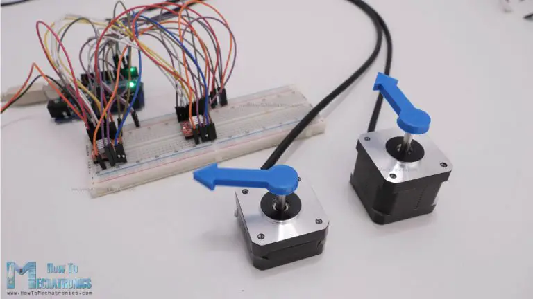
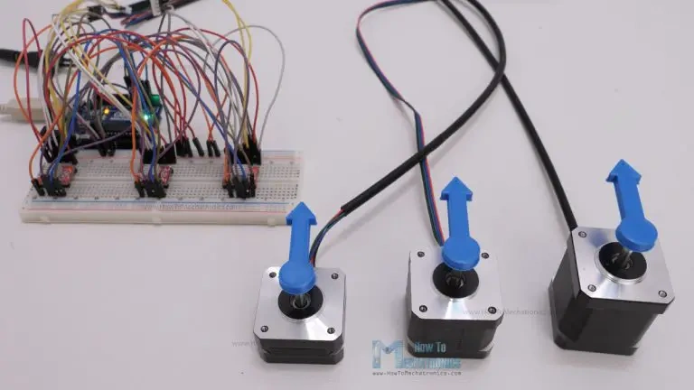
Controlling multiple stepper motors with AccelStepper library
    /*
        Controlling multiple steppers with the AccelStepper and MultiStepper library

         by Dejan, https://howtomechatronics.com
    */

    #include
    #include

    // Define the stepper motor and the pins that is connected to
    AccelStepper stepper1(1, 2, 5); // (Typeof driver: with 2 pins, STEP, DIR)
    AccelStepper stepper2(1, 3, 6);
    AccelStepper stepper3(1, 4, 7);

    MultiStepper steppersControl;  // Create instance of MultiStepper

    long gotoposition[3]; // An array to store the target positions for each stepper motor

    void setup() {

      stepper1.setMaxSpeed(1000); // Set maximum speed value for the stepper
      stepper2.setMaxSpeed(1000);
      stepper3.setMaxSpeed(1000);

      // Adding the 3 steppers to the steppersControl instance for multi stepper control
      steppersControl.addStepper(stepper1);
      steppersControl.addStepper(stepper2);
      steppersControl.addStepper(stepper3);
    }

    void loop() {
      // Store the target positions in the "gotopostion" array
      gotoposition[0] = 800;  // 800 steps - full rotation with quater-step resolution
      gotoposition[1] = 1600;
      gotoposition[2] = 3200;

      steppersControl.moveTo(gotoposition); // Calculates the required speed for all motors
      steppersControl.runSpeedToPosition(); // Blocks until all steppers are in position

      delay(1000);

      gotoposition[0] = 0;
      gotoposition[1] = 0;
      gotoposition[2] = 0;

      steppersControl.moveTo(gotoposition);
      steppersControl.runSpeedToPosition();

      delay(1000);
    }
Here we also need to include the MultiStepper class, and create an instance of it. Then we need to define an array, type “long”, which will be used for storing the target positions for our motors. In the setup section, we need to define the maximum speed values of the steppers and add the steppers to the previously created MultiStepper instance, which in my case I named it “steppersControl”.
In the loop section, we start by storing the target position values in the array that we previously created. I set the first stepper to move one rotation, the second, two rotations and the third one, three rotations. Then we can assign this array to the moveTo() function which will calculate the required speeds for all motors to arrive at those positions at the same time. Then we just have to call the runSpeedToPosition() function which will move the motors to their position. Though we should note that this function blocks the code until the steppers reach their target position. We could use the run() function instead, if we don’t want to block the code. We should also note that the MultiStepper class doesn’t support acceleration and deceleration.
TMC2208 Stepper Driver
The TMC2208 chip is made by Trinamic, a Germany based company specialized in motion control electronics. The TMC2208 is a silent stepper motor driver which can be also used as a direct replacement in systems designed for the A4988 or the DRV8825 drivers. It is widely used in desktop 3D printers, laser engravers, scanners and so on.
What sets this driver apart from the two others is its integrated interpolation unit which provides 256 subdivisions or microsteps. This allows for perfect sinusoidal control which is generated internally within the chip. This means that the driver will output 256 microsteps to the stepper motor, no matter what microstep resolution we have selected through the two MS pins, 2, 4, 8 or 16 microsteps. This provides smoother operation and reduces the burden of the microcontroller significantly.
This feature of the driver, in combination with the its noiseless current control StealthChop2 technology, provide that ultra-silent control of the stepper motors. Here’s a comparison of the noise levels between the three drivers.
The current rating of the TMC2208 is slightly higher than the A4988 driver, or it’s 1.2A with 2A peak current. For setting the current limit of the driver, again we can use the same method as explained for the other drivers. We need to measure the reference voltage with one probe on GND, and other on the whole right next to the Enable pin.
Although it can be used as direct replacement, the TMC2208 driver has a slightly different pinout compared to the A4988 driver. Here we only have two pins for selecting the microsteps resolution and for enabling the driver we need to connect the Enable pin to GND.
\
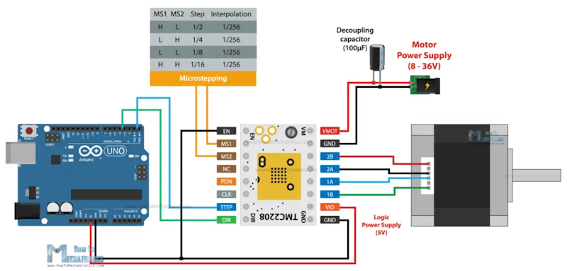
In terms of coding, it’s the same as the other two drivers.
The TMC2208 driver also have some other, more advanced features compared to the two other drivers, like for example, a simple-to-use UART interface which provides controlling the driver with just a single line, instead of the two Step and Dir pins. In addition to that I provides more tuning and control options.
Overall, the TMC2208 is a better driver that the A4988 and the DRV8825, but that’s normal as it comes with a higher price tag. Though, if you don’t need these extra features and the noise levels doesn’t concern you, are other two drivers are just great choice.
Source: https://howtomechatronics.com/tutorials/arduino/stepper-motors-and-arduino-the-ultimate-guide/