Semiconductor, Triac
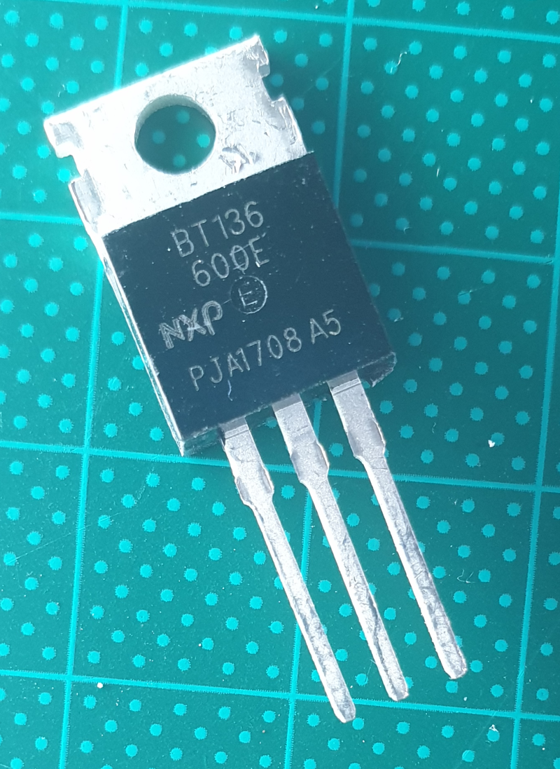
Triac BT136-600E

- On-State RMS Current - It RMS: 4A
- Non Repetitive On-State Current: 27A
- Rated Repetitive Off-State Voltage VDRM: 600V
- Off-State Leakage Current @ VDRM IDRM: 100uA
- On-State Voltage: 1.4V
- Holding Current Ih Max: 15mA
- Gate Trigger Voltage - Vgt: 700mV
- Gate Trigger Current - Igt: 11mA
- Package/Case: TO-2203

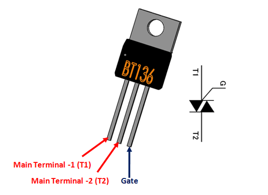
- 1: Main Terminal 1, Connected to Phase or neutral of AC mains
- 2: Main Terminal 2, Connected to Phase or neutral of AC mains
- 3: Gate, Used to trigger the SCR.
BT136 TRIAC Overview
The BT136 is TRIAC with 4A maximum terminal current. The gate threshold voltage of the BT136 is also very less so can be driven by digital circuits.
Since TRIACs are bi-directional switching devices they are commonly used for switching AC applications. So if you looking to switch of control (dim, speed control) an AC load which consumes less than 6A with a digital device like microcontroller or microprocessor then BT136 might be the right for you.
How to use BT136
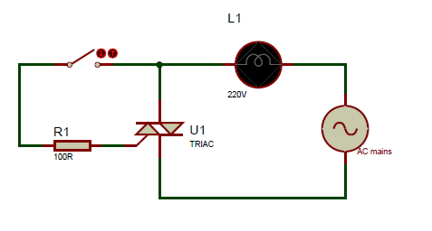
There are many different ways to use a TRIAC, since the device is bi-directional the TRIAC gate can be trigger with either positive voltage or negative voltage. So this allows the TIRAC to be operated in four different modes. You can read this article if you want to know more about the switching modes. A simple TRIAC switching circuit is shown below.

In this circuit the TRIAC can be turned using the switch, when the switch is pressed the TRIAC closes the connection for the AC bulb though the AC mains. For this to happen, the gate pin of the TRIAC should receive a voltage greater than the threshold gate voltage and should also get a current that is greater than gate trigger current. This will make the TRIAC turn on.
Since the TRIAC and SCR share most of the same characteristics, just like SCR the TRIAC will also not turn off when the gate voltage is removed. We need special type of circuit called commutation circuit to turn of the SCR again. This commutation is normally done by reducing the load current (forced commutation) less than the holding current. To put it simple the TRIAC will remain turned on only till the load current is greater than the holding current of the TRIAC.
Note: Commutation is not required in AC switching circuits because the TRIAC will not latch in on state since the AC voltage reaches zero for every half cycle.
Other than controlling through switch the BT136 can also be controlled through a microcontroller or a microprocessor. To do this we need an Opto-isolator like MOC3021 to isolate the AC circuit form Digital electronics. This way the Load can not only be switched but also the output coltage can be controlled by using PWM signals for fast switching.
TRIAC Application Tips
Since TRIACS deal with AC voltages, the circuit involving them has to be designed properly to aboid problem some tips are shared below
All TRIAC circuits suffer from an effect called Rate Effect. This occurs when the TRIAC is switching frequently and a sudden high voltage occurs at either main terminal of the TRIAC and damages the TRIAC itself. It can be avoided by using a snubber circuit.
Similarly there is another effect called backlash effect. This occurs due to the capacitance that gets accumulated between the two terminals of the MT1 and MT2 of the TRIAC. Due to this the TRIAC will not turn on even if the gate voltage is applied. This problem can be solved by providing a resistance in series for the capacitance to discharge.
When controlling the output AC voltage for dimmer or speed control applications a Zero crossing method is always recommended to be used.
In switching circuits the TRIAC is easily subjected to harmonics and EMI interference hence should be isolated from other digital electronics.
There is chance of backward current when the TRIAC is switching inductive loads, so an alternate discharge path has to be provided for the load to drain the inrush current.
BT136-600E, #30, 1.05.B>br>