|
|
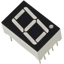
7-Segment Display
|
An LED or Light Emitting Diode, is a solid state optical PN-junction diode which emits light energy in the form of “photons” when it is forward biased by a voltage allowing current to flow across its junction, and in Electronics we call this process electroluminescence.
|
|
The actual colour of the visible light emitted by an LED, ranging from blue to red to orange, is decided by the spectral wavelength of the emitted light which itself is dependent upon the mixture of the various impurities added to the semiconductor materials used to produce it.
Light emitting diodes have many advantages over traditional bulbs and lamps, with the main ones being their small size, long life, various colours, cheapness and are readily available, as well as being easy to interface with various other electronic components and digital circuits.
But the main advantage of light emitting diodes is that because of their small die size, several of them can be connected together within one small and compact package producing what is generally called a 7-segment
|
|
The 7-segment display, also written as “seven segment display”, consists of seven LEDs (hence its name) arranged in a rectangular fashion as shown. Each of the seven LEDs is called a segment because when illuminated the segment forms part of a numerical digit (both Decimal and Hex) to be displayed. An additional 8th LED is sometimes used within the same package thus allowing the indication of a decimal point, (DP) when two or more 7-segment displays are connected together to display numbers greater than ten.
Each one of the seven LEDs in the display is given a positional segment with one of its connection pins being brought straight out of the rectangular plastic package. These individually LED pins are labelled from a through to g representing each individual LED. The other LED pins are connected together and wired to form a common pin.
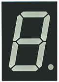
So by forward biasing the appropriate pins of the LED segments in a particular order, some segments will be light and others will be dark allowing the desired character pattern of the number to be generated on the display. This then allows us to display each of the ten decimal digits 0 through to 9 on the same 7-segment display.
The displays common pin is generally used to identify which type of 7-segment display it is. As each LED has two connecting pins, one called the “Anode” and the other called the “Cathode”, there are therefore two types of LED 7-segment display called: Common Cathode (CC) and Common Anode (CA).
The difference between the two displays, as their name suggests, is that the common cathode has all the cathodes of the 7-segments connected directly together and the common anode has all the anodes of the 7-segments connected together and is illuminated as follows.
-
The Common Cathode (CC) – In the common cathode display, all the cathode connections of the LED segments are joined together to logic “0” or ground. The individual segments are illuminated by application of a “HIGH”, or logic “1” signal via a current limiting resistor to forward bias the individual Anode terminals (a-g).
Common Cathode 7-segment Display
-
The Common Anode (CA) – In the common anode display, all the anode connections of the LED segments are joined together to logic “1”. The individual segments are illuminated by applying a ground, logic “0” or “LOW” signal via a suitable current limiting resistor to the Cathode of the particular segment (a-g).
Common Anode 7-segment Display
In general, common anode displays are more popular as many logic circuits can sink more current than they can source. Also note that a common cathode display is not a direct replacement in a circuit for a common anode display and vice versa, as it is the same as connecting the LEDs in reverse, and hence light emission will not take place.
Depending upon the decimal digit to be displayed, the particular set of LEDs is forward biased. For instance, to display the numerical digit 0, we will need to light up six of the LED segments corresponding to a, b, c, d, e and f. Then the various digits from 0 through 9 can be displayed using a 7-segment display as shown.
7-Segment Display Segments for all Numbers.
Then for a 7-segment display, we can produce a truth table giving the individual segments that need to be illuminated in order to produce the required decimal digit from 0 through 9 as shown below.
Driving a 7-segment Display
Although a 7-segment display can be thought of as a single display, it is still seven individual LEDs within a single package and as such these LEDs need protection from over current. LEDs produce light only when it is forward biased with the amount of light emitted being proportional to the forward current.
This means then that an LEDs light intensity increases in an approximately linear manner with an increasing current. So this forward current must be controlled and limited to a safe value by an external resistor to prevent damage to the LED segments.
The forward voltage drop across a red LED segment is very low at about 2-to-2.2 volts, (blue and white LEDs can be as high as 3.6 volts) so to illuminate correctly, the LED segments should be connected to a voltage source in excess of this forward voltage value with a series resistance used to limit the forward current to a desirable value.
Typically for a standard red coloured 7-segment display, each LED segment can draw about 15 mA to illuminated correctly, so on a 5 volt digital logic circuit, the value of the current limiting resistor would be about 200Ω (5v – 2v)/15mA, or 220Ω to the nearest higher preferred value.
Example
Extra info 7 segment Display
Ref: http://www.electronics-tutorials.ws/blog/7-segment-display-tutorial.html
|