KEYES 3.3V / 5V TTL Logic Level Converter Module
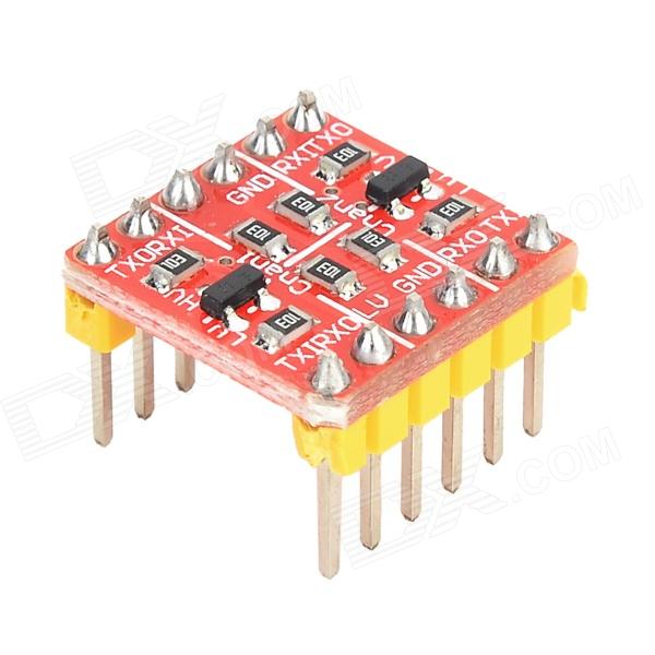
Two-way conversion: high level to low level, or low to high; Single conversion: high level to low level; Size: 1.5 x 1.5cm; Can plug in breadboard directly.
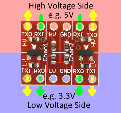
Take high voltage of 5V and low voltage of 3.3V for example: HV connect to 5V power supply, LV to 3.3V; GND connect to negative port, RXI input 5V TTL.
Board Overview
The LLC is designed to be very easy to use. Silkscreen indicators help identify which pins do what. There are twelve pins total – six on each side. We can divide them into groups of three to more clearly define how they relate:
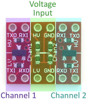
The middle section of the board is where the reference supply for your high and low voltages should go. Supplying voltage to all four of these pins is required. If you’re converting 3.3V to 5V (and vice-versa), for example, you’d run 5V into the “HV” side, and 3.3V into the “LV” input. Make sure each is grounded too!
The outer pins correspond to inputs and outputs for channels 1 and 2. Each channel has one voltage divider and one MOSFET shifter.
The labels on these pins – “RXI”, “RXO”, “TXI”, and “TXO” – help describe what each pins does:
-
RXI – High voltage input to voltage divider from high-voltage device. Signal will be shifted down and sent to low-voltage device on “RXO” pin.
-
RXO – Low voltage output from voltage divider to low-voltage device. Signal is shifted down from “RXI” input.
-
TXI – Low voltage input/output of MOSFET circuit. This pin interacts with “TXO” on the high side. Bi-directional, but this is the only shifter that will shift from low to high.
-
TXO – High voltage input/output of MOSFET circuit. This pin interacts with “TXI” on the low side. Bi-directional, but this is the only shifter that will shift from low to high.
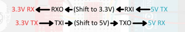
To send a signal from the low-voltage side to the high-voltage side (e.g. from 3.3V to 5V), the signal must be input at “TXI”. It’ll pass through the converter and come out as a higher voltage on the “TXO” (transmit output) pin.
On the other hand, a signal that strictly travels from high to low-voltage should pass from “RXI” to “RXO”.
Sending a signal from the high side to the low side is less restricted. We can use either the bi-directional channel or the voltage divider, but we may need to leave the bi-directional channel for converting from low-to-high.
Using this board is probably a lot easier than the length of this page would imply. Let’s look at some example configurations next.
Hookup Examples
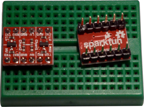
Assembly
Before you can plug the converter into your system, you’ll need to solder something into it. There are a lot of options here. You could solder straight male headers in, and plug it right into a breadboard. Or perhaps you want to solder wires directly into it. Pick an assembly method that melds with how you intend to use the board.>br>
Using the LLC for Serial
Converting voltages between serial devices is the part the LLC was born to play – that’s why it has the ‘RX’ and ‘TX’ labels. Lets say, for example, you have an Electric Imp – which has a maximum voltage of 3.3V – plugged into a Electric Imp Breakout Board and connected up to a standard Arduino Uno. Here’s how you might wire the two together, using an LLC to convert logic levels:
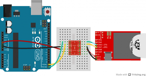
All of these ‘RX’, ‘RXI’, ‘RXO’, and even ‘RX0’ labels can get confusing. Remember ‘I’ stands for Input and ‘O’ stands for Output. If the Electric Imp sends a signal out of it’s ‘TX’ pin it’ll go into the ‘TXI’ pin on the LLC, get shifted up to 5V and come out the ‘TXO’ pin, and finally run into ‘RX’ on the Arduino.
Using the LLC for SPI
A standard SPI connection requires four wires – MOSI, MISO, SCLK, and CS – so we’ll need to use every pin on the LLC to shift this interface.
Let’s say, for example, you want to hook up an Arduino (again, running at 5V) to an ADXL345 Breakout Board. The ADXL345 has an operating range of 2.0-3.6V, so we’ll run it at 3.3V. Here’s how you might connect the two over an SPI interface, with an LLC in between:
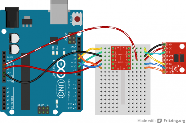
This hookup is weird because three wires are inputs to the ADXL345 and only one is an output. We can take advantage of the bi-directional ability of the TXI-to-TXO line to pass a signal (SCL in this example) from the high side to the low side.
Using the LLC for I2C
I2C is another weird situation where both wires – SDA and SCL – need to be bi-directional. So to use the LLC for an I2C interface, we need to take advantage of both bi-directional shifters on the board.
Let’s switch it up even further here. What if we had a 3.3V microcontroller trying to communicate with a 5V sensor. How about an Arduino Due trying to get the time from a 5V-only Real-Time Clock Module. Here’s how we might hook the two up using an LLC:
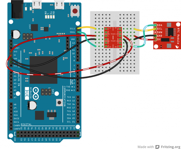
For I2C, this hookup is the same regardless of which of the two devices (master or slave) is low-voltage. Each wire should pass through a TXI-to-TXO converter.
Ref: learn.sparkfun.com
|