|
|
15. 7 segment LED Display 1.8" Blue Common Cathode with Shift Register 74HC595N
Big 7-segment displays have more than one LED in series per segment. Usually three. The DP has usually a single LED. Thats why I don't use resistors. For the dot you should use one.
For more info. (Datasheets)
Starting project.
Put the 74HC595N and the 7 Segment Display on the board.
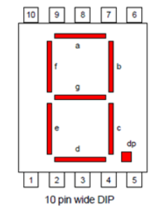
The pinlayout from the blue segment display (18011AB) differs slightly from the red one.
Pins:
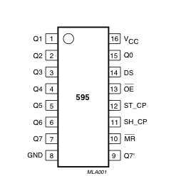
| 74HC595N | 7 segment display | Arduino |
 |
 |
|
| pin 1 | Pin 10 | -- |
| pin 2 | Pin 9 | -- |
| pin 3 | Pin 8 | -- |
| pin 4 | Pin 7 | -- |
| pin 5 | Pin 6 | -- |
| pin 6 | Pin 3 | -- |
| pin 7 | Pin 1 | -- |
| pin 8 | -- | GND |
| pin 9 | -- | -- |
| pin 10 | -- | 5V |
| pin 11 | Pin 8 | -- |
| pin 12 | Pin 7 | -- |
| pin 13 | -- | GND |
| pin 14 | Pin 4 | -- |
| pin 15 | Pin 2 | -- |
| pin 16 | -- | 5V |
| -- | Pin 4 | GND |
Code
const int dataPin = 4;  // 74HC595 pin 14
const int latchPin = 7; // 74HC595 pin 12
const int clockPin = 8; // 74HC595 pin 11

//const char common = 'a';    // common anode
const char common = 'c';    // common cathode
byte digits[10] = {
  B10101111, B00000110, B11001101, B11001110, B01100110, B11101010, B11101011, B00001110, B11101111, B11101110
};

bool decPt = false;  // decimal point display flag

void setup() {
  pinMode(dataPin, OUTPUT);
  pinMode(latchPin, OUTPUT);
  pinMode(clockPin, OUTPUT);
}

void loop() {
  for (int i = 0; i <= 9; i++) {
    byte bits = digits[i];

    if (decPt) {
      bits = bits | B00010000;  // add decimal point if needed
    }

    myfnUpdateDisplay(bits);    // display alphanumeric digit
    delay(1000);                 // pause for second
  }
}

void myfnUpdateDisplay(byte eightBits) {
  if (common == 'a') {                  // using a common anonde display?
    eightBits = eightBits ^ B11111111;  // then flip all bits using XOR
  }
  digitalWrite(latchPin, LOW);  // prepare shift register for data
  shiftOut(dataPin, clockPin, LSBFIRST, eightBits); // send data
  digitalWrite(latchPin, HIGH); // update display
}
Download : ino
|